The provided text is a detailed explanation of a multicluster architecture for deploying a high-availability (HA) and disaster recovery (DR) service in an OpenShift environment that uses a global load balancer and a federated service mesh (FSEM). The architecture is designed to handle stateless workloads, which are those that do not rely on a single point of failure. The approach involves creating a federation of service meshes across multiple clusters, each with its own mesh control plane and a peer control plane. The global load balancer manages the entire data center failures, while the mesh federation mitigates individual service failures.
The architecture involves the following steps:
1. **Configuring a global load balancer**: The global load balancer is configured with the global load balancing API, which is used to distribute incoming traffic across the cluster. The load balancer is configured with a selector that determines which clusters to route traffic to based on the requested service and the mesh federation configuration.
2. **Creating a federated service mesh**: The service mesh federation is configured using the Istio and OpenShift Service Mesh (OSM) v3.0 federation, which is a distributed service mesh that leverages multiple clusters. The federation is configured with multiple primary clusters and a single mesh control plane
Well-designed architecture requires service availability and the ability to contend with the unexpected. You can create a high level of resilience, covering both high availability (HA) and disaster recovery (DR), with a combined approach that leverages a global load balancer and a federated service mesh. The global load balancer manages entire data center failures, and the mesh federation mitigates individual service failure. This architectural approach is suitable for stateless workloads, but additional effort is required to get the same results on a stateful workload. In this article, I focus on stateless workloads.
This architectural approach is not new. It was first demonstrated several years ago during a presentation at KubeCon and CloudNativeCon North America 2023. However, at that time, it wasn’t possible to recreate a similar architecture in Red Hat OpenShift. Now it’s possible, thanks to the release of Red Hat OpenShift Service Mesh 3.0 and the introduction of Red Hat Connectivity Link.
In this article, I explore the benefits of this architectural approach, and discuss how to deploy and configure Red Hat OpenShift Service Mesh, Connectivity Link, and Red Hat Advanced Cluster Management (ACM).
Architecture
The high-level architecture of this approach is shown in Figure 1.

In this diagram, a client is making a request to an application composed of service A and service B. The application is deployed in two different OpenShift clusters, possibly in two different data centers.
Initially, the request is routed to one of the datacenters by the global load balancer. Within the diagram, the global load balancer decided to route the request to the left-side OpenShift cluster. Notice the dotted line representing the possible alternative choice.
The request then hits the ingress gateway at the edge of the OpenShift cluster. The ingress gateway is a reverse proxy that contains the intelligence to route requests originating from outside the cluster to the appropriate pods within the cluster and the service mesh. The ingress gateway is an entrance into the service mesh.
The gateway then proceeds to route the request to Service A. The gateway has two options: Route the request to the local instance of service A, or to the remote instance. Under normal circumstances, the local instance is preferred. But, in the event that the local service instance is unavailable, the request can be routed to the east-west gateway, which forwards it to the service A instance on the other cluster (depicted on the right-side of the diagram).
The east-west gateway is a component that enables federating service meshes from two or more OpenShift clusters. It has the awareness of where the east-west gateways of other clusters are located and how to route requests to and from other clusters.
Within this architecture, the request hits service A in the left side cluster. Service A needs to call service B. Another request is created and sent. The service mesh intercepts this request and again makes the decision of whether to forward this request locally or to a remote cluster.
In the event that a cluster has a problem, or the ingress gateway is unavailable, the global load balancer routes the request to another cluster that is available. Furthermore, if one of the services involved in the request has a failure, then the service mesh has the ability to route the request to another cluster.
Let’s see how to establish this architecture by first creating a federated service mesh and then layering on a global load balancer.
Federated the Service Mesh
We’re going to configure a OpenShift Service Mesh (based on upstream Istio) federation using the multi primary on different networks approach, illustrated in Figure 2.
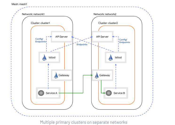
This service mesh federation style is suitable when a mesh is stretched across multiple clusters and the software-defined network (SDN) of the clusters are separate. This approach also has the added benefit that it does not feature a single mesh control plane, but each cluster (there can be more than two) carries a peer control plane.
There are three steps in configuring this type of mesh federation:
- Connect the mesh control plane (
istiod) with the remote cluster API servers (by default, it’s already connected with the local cluster control plane). - Create the east-west gateway to allow ingress traffic from remote endpoints of the mesh.
- Establish trust between the various mesh control planes.
Connect the mesh control plane (istiod) with the remote cluster API servers
We can add this fragment to our OpenShift Service Mesh v3.x deployment:
     meshID: default
     multiCluster:
       clusterName: ${CLUSTER_NAME}
     network: network-${CLUSTER_NAME}
This is the naming scheme in use:
- Mesh name:
default - Cluster name:
${CLUSTER_NAME} - Network name:
network-${CLUSTER_NAME}
In this example, I’ve parametrized the clusterName and the network name based on the cluster for which this manifest is being deployed.
We also need to add the topology.istio.io/network: network-${CLUSTER_NAME} label to the mesh’s namespace.
We also need secrets that allow istiod to connect to the remote API servers. To create these secrets, we can rely on Red Hat Advanced Cluster Management for Kubernetes to manage the configuration.
For each cluster participating in the mesh, this manifest must be created in the namespace associated with the target cluster within the hub cluster:
apiVersion: authentication.open-cluster-management.io/v1beta1
kind: ManagedServiceAccount
metadata:
 name: istio-reader-service-account
 labels:
   app: search
spec:
 rotation: {}
For each cluster participating in the mesh, this manifest also must be created in the namespace associated with the target cluster within the hub cluster:
apiVersion: rbac.open-cluster-management.io/v1alpha1
kind: ClusterPermission
metadata:
 name: istio-reader-service-account
 labels:
   app: search
spec:
 clusterRoleBinding:
   subject:
     kind: ServiceAccount
     name: istio-reader-service-account
     namespace: open-cluster-management-agent-addon
   roleRef:
     apiGroup: rbac.authorization.k8s.io
     kind: ClusterRole
     name: istio-reader-clusterrole-istio-system
These resources generate a secret in the same namespace with the service account token of the istio-reader service account that was created in each managed cluster when OpenShift Service Mesh was deployed. Once the secret has been created, the following ACM policy can be applied:
{{hub $clusterName := .ManagedClusterName hub}}
{{hub range (lookup "cluster.open-cluster-management.io/v1" "ManagedCluster" "" "").items hub}}
{{hub if eq (index .metadata.labels "servicemesh-federation") "enabled" hub}}
{{hub if not (eq .metadata.name $clusterName) hub}}
- complianceType: mustonlyhave
 objectDefinition:
   apiVersion: v1
   kind: Secret
   metadata:
     name: istio-remote-secret-{{hub .metadata.name hub}}
     namespace: 'istio-system'
     labels:
       "istio/multiCluster": "true"
     annotations:
       "networking.istio.io/cluster": env.ctx
   type: Opaque
   stringData:
     {{hub .metadata.name hub}}: |-
       apiVersion: v1
       kind: Config
       clusters:
       - name: {{hub .metadata.name hub}}
         cluster:
           certificate-authority-data: {{hub (index .spec.managedClusterClientConfigs 0).caBundle hub}}
           server: {{hub (index .spec.managedClusterClientConfigs 0).url hub}}
       contexts:
       - name: istio-reader-service-account/{{hub .metadata.name hub}}
         context:
           cluster: {{hub .metadata.name hub}}
           namespace: istio-system
           user: istio-reader-service-account
       users:
       - name: istio-reader-service-account
         user:
           token: {{hub (lookup "v1" "Secret" .metadata.name "istio-reader-service-account").data.token | base64dec hub}}
       current-context: istio-reader-service-account/{{hub .metadata.name hub}}
{{hub end hub}}
{{hub end hub}}
{{hub end hub}}
This policy generates a series of secrets in each of the managed clusters within the istio-system namespace. Each of the generated secrets contains a kubeconfig file that allows istiod to connect to one of the remote clusters.
East-west gateways
Next, create an east-west gateway in each of the federated clusters. You can use this script to generate the east-west gateways. You must provide the network name as an input parameter. Be sure to reference the values used previously.
Place the generated resources from that script under GitOps control (or even better, a generalized in a Helm chart for future reuse).
The gateways must be exposed through a LoadBalancer service, because they receive traffic from outside the cluster. Once the gateway is created, expose all services present in the local portion of the service mesh on the gateway with this manifest:
apiVersion: networking.istio.io/v1alpha3
kind: Gateway
metadata:
 name: cross-network-gateway
spec:
 selector:
   istio: eastwestgateway
 servers:
   - port:
       number: 15443
       name: tls
       protocol: TLS
     tls:
       mode: AUTO_PASSTHROUGH
     hosts:
       - "*.local"
Establishing trust
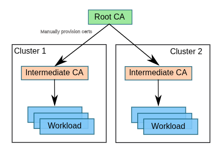
For encrypted communications to function properly between services spread across different clusters (and between sidecars and east-west gateways), a common root of trust for the various service mesh control planes must be created. The following diagram (Figure 3) depicts the configuration that we are aiming to achieve.
An Opaque secret (not a TLS secret type) named cacert must exist in the istio-system namespace. This secret must have the following keys:
ca-cert.pem: Intermediate CA certificateca-key.pem: Intermediate CA certificate keyroot-cert.pem: Root CA certificatecert-chain.pem: Concatenation of the intermediate CA certificate and root CA certificate
This setup can be automated in many ways. In my tests, I used the cert-manager operator and Red Hat Advanced Cluster Management for Kubernetes to do it. Figure 4 illustrates the approach.
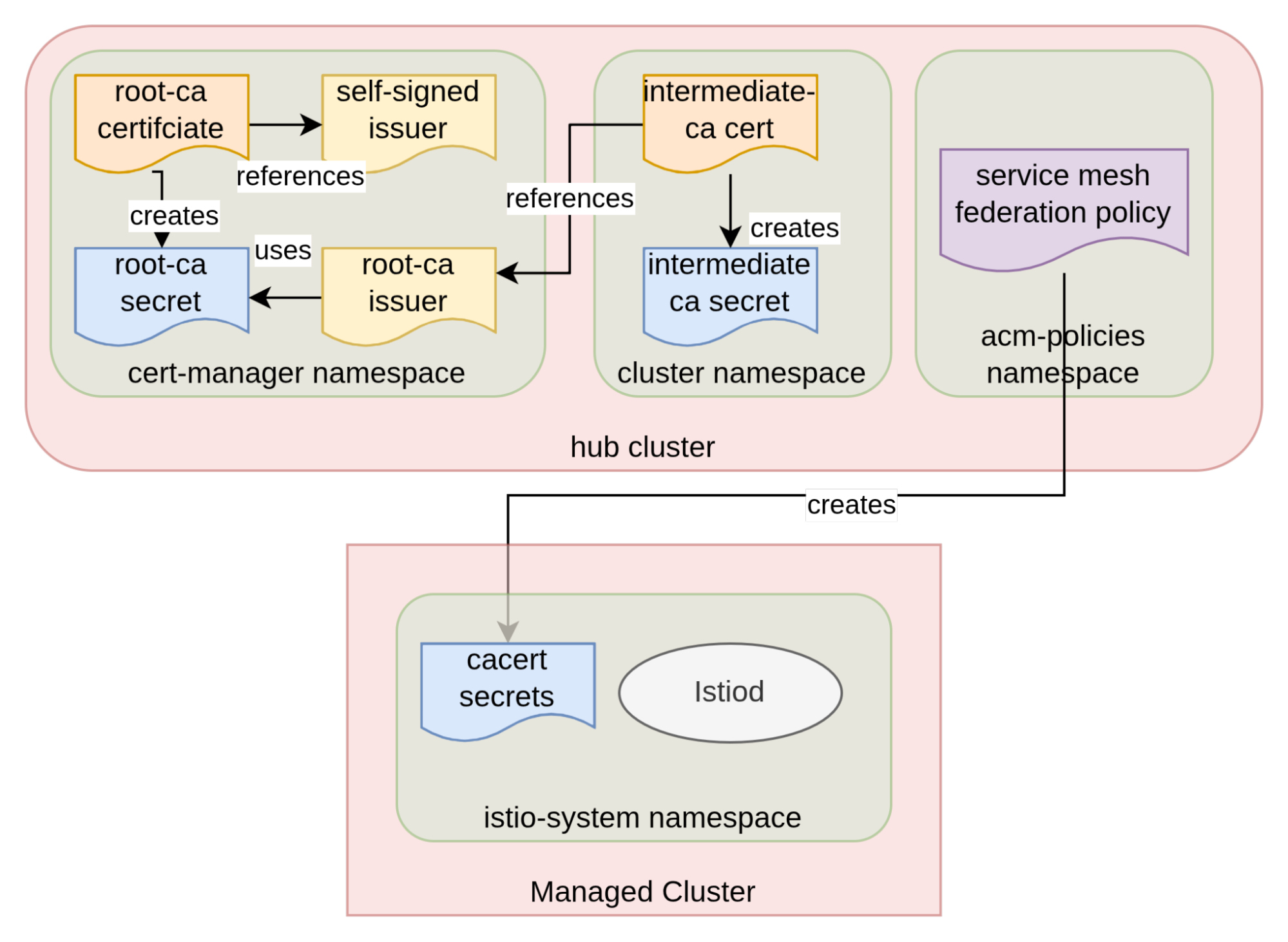
A root CA is created first from a self-signed cluster issuer, resulting in the creation of a secret containing the newly created certificate. Once that’s in place, we use the root-ca cluster issuer to create intermediate CAs, one for each managed cluster.
Finally, a Red Hat Advanced Cluster Management for Kubernetes policy can be used to create the cacert secret directly in the istio-system namespace of each of the managed clusters. This is the policy I used:
 - complianceType: mustonlyhave
   objectDefinition:
     apiVersion: v1
     kind: Secret
     metadata:
       name: cacerts
       namespace: 'istio-system'
     type: Opaque
     data:
       ca-cert.pem: {{hub (index (lookup "v1" "Secret" .ManagedClusterName "intermediate-ca").data "tls.crt") hub}}
       ca-key.pem: {{hub (index (lookup "v1" "Secret" .ManagedClusterName "intermediate-ca").data "tls.key") hub}}
       root-cert.pem: {{hub (index (lookup "v1" "Secret" "cert-manager" "root-ca").data "tls.crt") hub}}
       cert-chain.pem: {{hub (list ((index (lookup "v1" "Secret" .ManagedClusterName "intermediate-ca").data "tls.crt") | base64dec) ((index (lookup "v1" "Secret" "cert-manager" "root-ca").data "tls.crt") | base64dec)) | join "\n" | base64enc hub}}
With this in place, end-to-end mTLS connections are enabled, and can flow between endpoints in different clusters.
Configuring the global load balancer
The next step is to configure the global load balancer for our deployment using Red Hat Connectivity Link (based on the upstream project Kuadrant). Connectivity Link works by enhancing the gateway belonging to a gateway API system. In particular, Connectivity Link supports gateways implemented by Envoy. One of the capabilities that can be enabled is the ability to configure DNS addresses that can be used for the purpose of operating as global load balancers. For more information on this approach, read Global load balancer approaches.
This step is relatively straightforward when the DNS exposes an API, as in the case of cloud providers. As of the release of Red Hat Connectivity Link v1.1, there’s support for configuring on-prem global load balancers (at the time of writing, this capability is in Tech Preview).
Aside from deploying the Red Hat Connectivity Link operator, there are three configurations to implement:
- Enable Gateway API
- Deploy Kuadrant CoreDNS
- Create HttpRoutes and DNS policies
Enable gateway API
OpenShift Service Mesh 3.x fully supports the gateway API, but this feature must be enabled by deploying the gateway API CRDs (this step is not needed with OpenShift 4.19 and later versions). This can be done by applying the manifests as described in this resource.
Deploy Kuadrant CoreDNS
You must create a zone delegation, or forwarding, from within the upstream DNS to instances of CoreDNS deployed within your clusters. Figure 5 depicts this configuration,
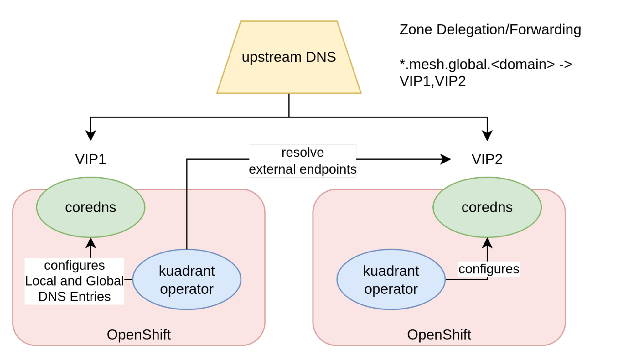
When DNS requests are issued for the delegated zone, the upstream DNS forwards the request to one of the CoreDNS instances. These instances are exposed through a LoadBalancer Service, so they have an associated VIP. The zone delegation is configured to forward requests to these VIPs.
The content of the CoreDNS instance is configured by the Kuadrant operator based on the state of the cluster. For each managed endpoint, Kuadrant creates two DNS entries: A local entry (for internal use) and a global entry (for external consumption). There is a loose coordination protocol in place between the Kuadrant operators of the OpenShift clusters involved in this setup. For each configured globally load balanced service, each operator tries to resolve the local name at each of the external CoreDNS instances. This allows an operator in a particular cluster to discover endpoints exposed in other clusters. Once this information is retrieved, it is merged into the global DNS record. This creates DNS records with multiple IPs (DNS records suitable for global load balancing).
In order to create this architecture, we must first deploy CoreDNS, and then configure the Kuadrant operator to manage the local instance and connect to the remote instances.
Install CoreDNS by deploying the Helm chart associated with the Kuadrant project. After the chart is deployed, a corefile can be added by creating a kuadrant-coredns configmap, this is an example of what the corefile might look like:
kdrnt {
    debug
    errors
    health {
        lameduck 5s
    }
    ready
    log
    transfer {
        to *
    }
    kuadrant
    prometheus 0.0.0.0:9153
}
global.${PLATFORM_BASE_DOMAIN} {
    debug
    errors
    log
    geoip GeoLite2-City-demo.mmdb {
        edns-subnet
    }
    metadata
    transfer {
        to *
    }
    kuadrant
    prometheus 0.0.0.0:9153
}
As shown in the Corefile above, two zones are configured. The first zone is for the internal records. The second is for the global record. In this example, the external zone is parametrized to global.${PLATFORM_BASE_DOMAIN}.
To inform Kuadrant of where the other CoreDNS instances are located (what the corresponding VIPs are), a secret must be configured containing a list of the nameservers (VIP and port) along with the zone they manage. With GitOps, this configuration isn’t straightforward to create. The VIPs of the LoadBalancer service exposing CoreDNS are assigned after creation. They cannot normally be set by the user. Once again, policies within Red Hat Advanced Cluster Management helps streamline this configuration. First, create a ManagedClusterView to reflect the CoreDNS LoadBalancer services in the hub cluster:
apiVersion: view.open-cluster-management.io/v1beta1
kind: ManagedClusterView
metadata:
 labels:
   coredns-service: ''
 name: coredns-service
spec:
 scope:
   apiGroup: ""
   kind: Service
   name: kuadrant-coredns
   namespace: kuadrant-coredns
   version: v1
Use a policy to create the secret (which must be deployed to every managed cluster):
 - complianceType: mustonlyhave
   objectDefinition:
     apiVersion: v1
     kind: Secret
     metadata:
       name: core-dns
       namespace: bookinfo
     type: kuadrant.io/coredns
     stringData:
     {{hub- $servers := list hub}}
     {{hub- range $mcv := (lookup "view.open-cluster-management.io/v1beta1" "ManagedClusterView" "" "" "coredns-service").items hub}}
       {{hub- $server := (index $mcv.status.result.status.loadBalancer.ingress 0).ip hub}}
       {{hub- $servers = append $servers (printf "%s:53" $server) hub}}
     {{hub- end hub}}
       NAMESERVERS: {{hub $servers | join "," hub}}
       ZONES: 'global.${PLATFORM_BASE_DOMAIN}'
This policy creates secrets similar to this:
kind: Secret
apiVersion: v1
metadata:
 name: core-dns
 namespace: kuadrant-coredns
data:
 NAMESERVERS: 10.9.51.161:53,10.9.52.147:53,10.9.53.35:53
 ZONES: *.global.example.com
type: kuadrant.io/coredns
After CoreDNS is deployed and configured as described above, you can start creating DNS records.
Create the gateway, DNS policy, and HttpRoute
Currently in Kuadrant, DNS records are created based on the Gateway configuration. For example:
apiVersion: gateway.networking.k8s.io/v1
kind: Gateway
metadata:
 name: main
 labels:
   kuadrant.io/lb-attribute-geo-code: ${CLUSTER_NAME}
spec:
 gatewayClassName: istio
 listeners:
   - allowedRoutes:
       namespaces:
         from: All
     hostname: '*.mesh.global.${PLATFORM_BASE_DOMAIN}'
     name: api
     port: 443
     protocol: HTTPS
     tls:
       certificateRefs:
         - group: ''
           kind: Secret
           name: gateway-ingress-certs-tls
       mode: Terminate
Next, add a DNSPolicy so that DNS records are created for the Gateway instance:
apiVersion: kuadrant.io/v1
kind: DNSPolicy
metadata:
 name: main
spec:
 targetRef:
   group: gateway.networking.k8s.io
   kind: Gateway
   name: main
 providerRefs:
   - name: core-dns
With this in place, you have DNS resolution for names in the *.mesh.global.ocp.rht-labs.com domain. For example:
nslookup a.mesh.global.example.com
Server:         10.9.51.161
Address:        10.9.51.161#53

Name:   a.mesh.global.example.com
Address: 10.9.51.162
Name:   a.mesh.global.example.com
Address: 10.9.52.148
Name:   a.mesh.global.example.com
Address: 10.9.53.36
Notice that a.mesh.global.example.com was used in the request (a wildcard DNS entry), so any value before mesh resolves properly.
At this point, HTTPRoutes can be created. The following example illustrates how to route requests to the sample bookinfo application:
kind: HTTPRoute
metadata:
name: bookinfo
spec:
parentRefs:
- name: bookinfo
group: gateway.networking.k8s.io
kind: Gateway
hostnames:
- "bookinfo.mesh.global.${PLATFORM_BASE_DOMAIN}"
rules:
- matches:
- path:
type: Exact
value: /productpage
- path:
type: PathPrefix
value: /static
- path:
type: Exact
value: /login
- path:
type: Exact
value: /logout
- path:
type: PathPrefix
value: /api/v1/products
backendRefs:
- group: ''
kind: Service
name: productpage
port: 9080
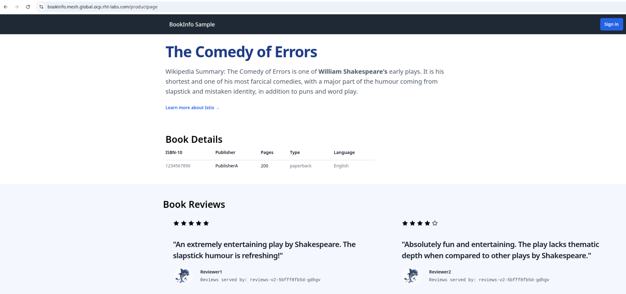
weight: 1With all configuration in place, launch a web browser and navigate to the the global fully-qualified domain name (FQDN) displaying the bookinfo application (Figure 6).
Multicluster architecture
In this article, I’ve demonstrated how you can build a highly resilient multicluster architecture. By leveraging solutions such as Red Hat Service Mesh Federation and Red Hat Connectivity Link, you can create deployments that are resilient to the loss of individual components or entire data centers. Stateful workloads have unique considerations, and could be the subject of a subsequent article in the future, but the topologies described in this article are well suited for stateless workloads.
The post Multicluster resiliency with global load balancing and mesh federation appeared first on Red Hat Developer.